
Construction of Cycloid Gear Motor
Release Time :
2025-01-08
Source :
network
Author:
Guangdong Yongkun Motor Co., Ltd
Cycloid gear hydraulic motor is also a commonly used low-speed motor with compact structure and low price for small and medium power static hydraulic drive devices.
It has a simple structure and low technical threshold. It shares many similarities with the fully hydraulic steering gear widely used in medium and low-speed walking machinery in terms of technology, making it easy to form a batch advantage and therefore a darling of the market.
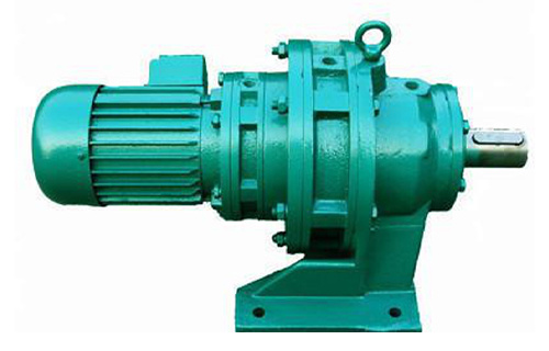
Cycloidal gear motor
Cycloid gear motor is a type of gear type hydraulic component with internal meshing. Its core meshing pair is a cleverly designed pair of spur gear internal meshing pairs with a "one tooth difference". The tooth profile of the stator internal ring is cylindrical, known as "needle teeth"
Or simply a set of cylindrical rollers that can rotate inside the outer ring sleeve; The external gear that meshes with the needle ring is a cycloidal gear. The number of teeth on the external gear is one less than the number of needle teeth on the ring gear
The meshing pair with similar or fewer tooth differences and the cycloidal pinwheel reducer known for its large reduction ratio use the same meshing principle.
This structure is also seen in cycloidal gear pumps, which are often used as oil pumps for internal combustion engines and as supplementary oil pumps for axial piston pumps.
However, the internal and external gears of such high-speed cycloidal pumps rotate around their respective fixed axes, and the oil entering from the suction port is transmitted through multiple teeth to the outlet.
The needle ring of a cycloidal motor is a fixed non rotating stator ring, and the cycloidal gear (rotor) contained inside rotates around its own axis
Along with its own axis, it revolves around the common axis of the stator ring and output shaft with a certain eccentricity.
This combination and configuration enable the various meshing pairs of its stator and rotor to convert the change in inter tooth volume into displacement every time they complete meshing, unlike the drive shaft of the aforementioned cycloidal pump that only presses out one inter tooth volume of oil every revolution.
The center of the rotor and the inner cavity of the output shaft of the cycloidal gear motor are both provided with involute tooth shaped internal keyway holes, which are coupled by a spherical tooth shaped coupling between the two
The coupling transmits the torque generated by the hydraulic oil pressure difference between adjacent teeth of the rotor, and compensates for the eccentric motion between the rotor axis and the output shaft.
Similar to plunger type components, the flow distribution of cycloidal gear motors also has two types: radial and end face, and is similar to the flow distribution device of multi acting internal curve motors
Multiple sets of distribution slots are distributed on a circumference, unlike the fixed axis cycloidal pump which only has one pair of inlet and outlet slots.
In a certain sense, the action mechanism of a cycloidal gear motor is roughly equivalent to that of a multi acting internal curve motor, except that the cylindrical space inside the plunger cylinder is replaced by a tooth valley enclosed between the stator, rotor, and front and rear end plates
And the pressure oil in this space directly acts on the rotor surface to generate torque without the need for intermediate force transmission components such as plungers. This structure allows the displacement and torque of the cycloidal motor to be several times that of a cycloidal pump with the same meshing parameters and pressure
gear motor,Gear motor,Cycloidal pin wheel reducer


Address: No.66 bis, Hetong Road, Dongfeng Town, Zhongshan City, Guangdong Province
Tel:0760-22189558
Mobile:13923325827

©2023 GUANGDONG YONGKUN MOTOR CO.,LTD All rights reserved


