
Installation method of small reduction motor
Release Time :
2025-08-01
Source :
network
Author:
YONGKUN
Installation method of small reduction motor
The characteristics of small reduction motors are efficiency and reliability, long working life, easy maintenance, and application. Its series can be divided into single-stage, two-stage, and three-stage gear reduction motors, and the installation and layout methods mainly include expansion type, coaxial type, and split type. 1. In the expansion type of two-stage cylindrical reduction motor, the gears are asymmetric relative to the support position. When the shaft undergoes bending and twisting deformation, the load is divided by the tooth width
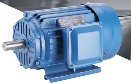
Small reduction motors have the characteristics of high efficiency, reliability, long service life, and simple maintenance and use. Its series can be divided into single-stage, two-stage, and three-stage gear reduction motors, with main installation and layout methods including expansion type, coaxial type, and split type.
Classification of main installation methods
1. Flange Mounting
characteristic:
By fixing the flange on the end face of the motor/reducer to the equipment, the axial space occupation is small, the structure is compact, and the anti torsion ability is strong.
Common types:
B5 flange (flange flange):
The flange is located at the rear of the motor (opposite to the output shaft), with the output shaft cantilevered out. Attention should be paid to the limit of cantilever load.
Applicable scenarios: In situations where space is limited and direct connection to loads (such as pulleys and gears) is required.
B14 flange (end face flange):
The flange is located on the output shaft side, and the output shaft is flush or inwardly contracted with the flange end face. Can withstand a certain radial force, with better connection rigidity.
Applicable scenario: It is necessary to directly connect the load shaft (such as mixing rod, conveyor roller) through a coupling or in situations where high coaxiality is required.
Special flanges (such as square flanges):
Customized design for specific device interfaces.
Advantages: Save installation space, resist torsion and load, easy to seal.
matters needing attention:
The flange bolts should be tightened evenly in diagonal order to avoid deformation.
The length of the output shaft cantilever should not be too long (B5 type), otherwise the shaft end load needs to be calculated.
The flange end face and equipment installation surface must ensure flatness and perpendicularity.
Foot Mounting
characteristic:
Fixed to the base with anchor bolts through the mounting feet (usually 2 or 4) at the bottom of the motor, providing stable support and good vibration resistance.
Common types:
B3 standard footrest: the most common, with mounting holes at the bottom.
B35 combination type: equipped with both foot base and flange (mostly B5), making installation more flexible.
Advantages: Strong load-bearing capacity, good heat dissipation (unobstructed bottom), easy maintenance (easy to disassemble).
matters needing attention:
The installation base should be flat and sturdy (such as steel plates or racks), avoiding soft support.
Use elastic shock absorbers (especially in high-frequency start stop scenarios) to reduce vibration transmission.
Strictly level to avoid bearing wear caused by uneven force on the motor housing.
Hollow Shaft Mounting
characteristic:
The output shaft of the reducer is a hollow shaft, which is directly fitted onto the equipment drive shaft through a locking assembly and locked.
Advantages:
Zero backlash transmission, high positioning accuracy.
Eliminating the coupling, the structure is extremely compact and the installation length is short.
Capable of transmitting high torque without the risk of keyway damage.
Applicable scenarios:
Equipment that requires direct drive of rollers, turntables, and winches (such as conveyor lines, indexing tables, and winches).
matters needing attention:
The device drive shaft must meet the requirements of size, tolerance, and surface hardness.
The expansion sleeve needs to be locked according to the specifications (torque wrench), and the tightening force should be checked regularly.
Disassembly requires a dedicated top thread, and maintenance is slightly more complicated. The installation method of small reduction motors needs to be selected comprehensively based on load characteristics, space limitations, and accuracy requirements. For high-frequency start stop equipment, flange installation (B14/B5)+high rigidity base+precision alignment is a reliable solution. As a manufacturer, providing clear installation guidelines and error prevention suggestions (such as bolt torque tables and alignment specifications) can significantly reduce customer failure rates and enhance product reputation.
Reducer,gear motor,gear reducer


Address: No.66 bis, Hetong Road, Dongfeng Town, Zhongshan City, Guangdong Province
Tel:0760-22189558
Mobile:13923325827

©2023 GUANGDONG YONGKUN MOTOR CO.,LTD All rights reserved


