
Worm gear reducer: principle and correct operation
Release Time :
2025-03-29
Source :
netwokr
Author:
Yongkun Motor
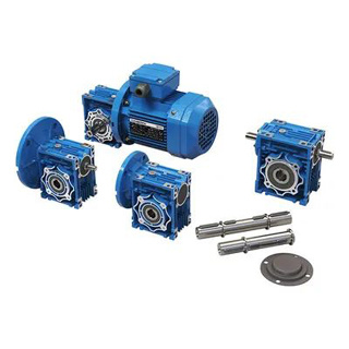
Worm gear reducer: principle and correct operation
1. Working principle of worm gear reducer
1. Basic structure and transmission mode
Core components:
Worm (active component): Similar to a screw, usually with a single or multiple heads (the more heads there are, the higher the transmission efficiency), rotating around its own axis.
Worm gear (driven component): Similar to a gear, but with a helical tooth profile, it rotates when meshing with a worm.
Box body: supports worm and worm gear, accommodates lubricating oil, and ensures transmission accuracy.
Transmission principle:
When the worm rotates, its helical teeth push the teeth of the worm wheel, converting the high-speed low torque of the worm into low-speed high torque of the worm wheel.
Transmission ratio: I=number of worm heads and worm gear teeth, for example, a single head worm with a 40 tooth worm gear has a transmission ratio of 40:1.
Movement direction: The axis of the worm and worm wheel is perpendicular to each other (usually at a 90 ° angle), and the rotation direction of the worm and worm wheel can be determined by the right-hand rule (for right-handed worms, use the right-hand rule, with four fingers pointing in the direction of worm rotation and the thumb pointing in the opposite direction to the direction of worm wheel circumferential velocity).
2. Main characteristics
advantage:
High transmission ratio (usually 10:1~80:1, or even higher), compact structure;
Smooth operation, low noise, suitable for precision transmission;
It has self-locking properties (when the worm lead angle is less than the friction angle, the worm wheel cannot drive the worm, which can prevent reverse rotation, such as elevator braking).
Disadvantages:
The transmission efficiency is relatively low (generally, the efficiency of a single head worm is about 50%~70%, and that of a multi head worm can reach over 80%);
Worm gear materials are mostly copper alloys (anti friction), which have higher costs;
High heat generation requires good lubrication and heat dissipation.
2、 Correct operation guide for worm gear reducer
1. Preparation before installation
Selection matching: Confirm that the rated torque, speed, transmission ratio of the reducer match the load requirements to avoid overload (actual load torque ≤ rated torque).
Cleaning inspection: Check the surface of the box, worm gear, and worm wheel for oil stains and impurities, and ensure that the gear meshing surface is intact.
Installation tools: Prepare torque wrench, dial gauge (to measure coaxiality), cleaning agent, etc.
2. Installation points
Coaxiality calibration:
The worm gear shaft and load shaft, worm gear shaft and motor shaft must be strictly coaxial (deviation ≤ 0.05mm), otherwise it will cause vibration, noise and gear wear. The position of the motor or reducer can be adjusted through shims, and the radial runout can be detected using a dial gauge.
Fixed method:
The box body needs to be firmly fixed on the frame with bolts, and the bolt torque should be tightened according to the manufacturer's instructions (to avoid loosening or excessive tightening that may cause deformation).
Coupling selection:
It is recommended to use elastic couplings (such as plum blossom couplings) to compensate for slight coaxiality errors and reduce impact loads.
3. Lubrication management
Lubricating oil selection:
High viscosity gear oil (such as ISO VG 220, 320) or worm gear specific oil (containing extreme pressure additives to reduce copper alloy wear) is usually used.
When the ambient temperature is low, choose low viscosity oil (such as VG 150 in winter), and when it is high temperature or heavy load, choose high viscosity oil (such as VG 460 in summer).
electrical machinery,gear motor,Reducer


Address: No.66 bis, Hetong Road, Dongfeng Town, Zhongshan City, Guangdong Province
Tel:0760-22189558
Mobile:13923325827

©2023 GUANGDONG YONGKUN MOTOR CO.,LTD All rights reserved


