
Is the fault of motor shaft breakage caused by the manufacturer or the user?
Release Time :
2024-09-06
Source :
network
Author:
YONGKUN
The shaft is the key to the connection between the motor product and the dragged equipment, and carries the responsibility of converting the kinetic energy of the motor. During the use of motors, there will always be some cases of broken shafts.
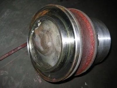
Most motor shaft breaks occur at the root of the shaft extension and the bearing root at the end of the shaft extension.
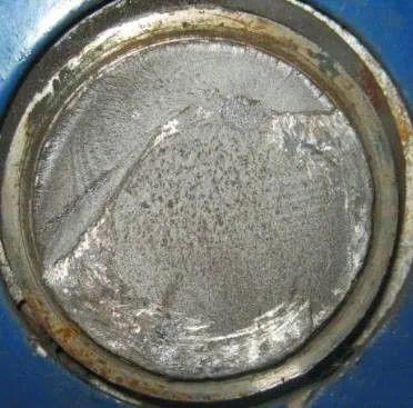
If the motor experiences shaft fracture, macroscopic observation and microscopic analysis should be conducted on the fracture surface to identify the location and cause of the fracture crack and fundamentally suppress the problem.
The fracture surface of the shaft is located in the transition fillet area where the bearing is installed on the shaft (at the root of the bearing installation). If the fracture is flat and perpendicular to the axis, there will be no necking or plastic deformation marks. The fatigue band is obvious, extending from the outer circle to the center, and the final instantaneous fracture area is less than 15% of the axial cross-sectional area.
The calculation and analysis of motor mechanics, as the motor shaft is a stepped shaft, the torque and stress at different stepped sections are different. When the motor is running, the shaft is subjected to the combined action of bending moment and torque. If the step portion is subjected to excessive stress, it may first initiate cracks and fracture at the transition arc of the step portion. Therefore, identifying the dangerous section where the motor shaft is subjected to force plays an important role in determining the cause of shaft fracture.
Induction of Reasons for Motor Shaft Fracture
The fracture of the motor shaft is the result of multiple factors combined. This article lists several common reasons:
1. Create potential quality issues. The fracture form of the motor shaft belongs to low stress rotational bending fatigue fracture, and the fundamental reason is that there are defects in the production and processing of the motor shaft, such as no process control requirements for the shoulder transition fillet, no heat treatment after welding, excessive inclusions in the weld layer, resulting in stress concentration at the shoulder fillet, fatigue cracking under the action of rotational bending moment, and ultimately leading to the fracture of the motor shaft.
2. Installation issues. If belt pulley transmission is used, excessive belt tension (greater than the recommended value by the belt manufacturer) increases the load on the motor shaft, which is a contributing factor to motor shaft fracture. If the motor installed with a coupling cannot guarantee the coaxiality between the motor and the equipment axis, it can also lead to fatigue fracture of the shaft.
3. Web plate axis fracture. Besides installation factors, irregular cracks often appear at the welding position of the web plate shaft. The problem of shaft breakage in this type of shaft is mostly solved by most motor manufacturers through annealing processes, where stress slots are machined at both ends of the web connecting the spindle.
Shaft shift
The motor should never be shifted at any time, as even a slight movement has little impact on the motor itself. If the shifting momentum reaches a certain level, specific problems such as increased current, motor temperature rise, and increased mechanical shock may occur, and other equipment may also be affected.
 Analysis of Reasons for Motor Shaft Offset
1. The mechanical center is not consistent with the magnetic field center.
When the motor is running, its rotor will be located at the center of the magnetic field, and there is a mechanical center between the rotor spindle and the two bearings (i.e. the position where the shoulders at both ends of the motor rotor are equidistant from the bearings). There may be inconsistencies between these two centers. If the shoulder spacing is adjusted based on the mechanical center during installation, when the motor starts, the rotor will automatically position at the center of the magnetic field, and the axial movement of the motor shaft will destroy the axial spacing adjusted during installation. When this deviation is small, the gear coupling can be compensated for by the reserved axial clearance between the inner and outer gear sleeves. If the axial clearance reserved for the coupling is exceeded, the coupling and the driven shaft will be subjected to axial external forces, causing friction on the end faces of the components and generating harmful effects such as heating.
2. For sliding bearing motors, errors may occur when the rotating shaft system is aligned with the coupling.
The misalignment of the shaft in the bearing will add significant additional torque to the bearing. Due to the fact that the motor rotor can move back and forth within a certain range in the axial direction and the axis center does not coincide, the coupling will generate a fixed axial force component. Under the action of the axial force component, the rotor will be pushed to one side against the magnetic field force, causing dynamic and static friction between the motor rotor oil shoulder and the Babbitt alloy outside the bearing.
3. The lift at both ends of the motor rotor does not meet the requirements.
Unreasonable lifting of the shaft necks at both ends of the motor can cause the rotor to overcome the magnetic field force and slide upwards towards the smaller end under the axial component of its own gravity. Therefore, a reasonable head at both ends of the motor shaft is the key to eliminating axial components. Due to the static deflection caused by the self weight of the rotor, it indicates that when the rotor is placed horizontally, both ends or the shaft neck will be lifted. The lift value measured by a precision level is commonly referred to as rotor lift. Given the various reasons for motor shaft offset, it is crucial to avoid problems during motor design, manufacturing, and installation. It is also essential to use necessary measures to suppress and prevent the occurrence of problems in the actual process. The fit between the shaft and rotor is an interference fit. If there is movement due to coordination issues, it is mostly due to the machining dimensions of the shaft. Because the inner diameter of the rotor shaft hole is determined by the stamping die, theoretically there should not be too much problem. The waveform spring pads at both ends of the bearing are not installed, or there is a quality issue with the waveform spring pads. Some motors have relatively strict requirements for shaft runout under operating conditions, and motor manufacturers solve this problem by adding corrugated spring pads. Some manufacturers also add retaining rings to the end caps of small motors with sealed bearings. The axial force generated by the fan is the axial force exerted by the wind on the fan blades during the operation of the motor, but the amount of play generated is very small. Improper selection of the fit between the bearing and the end cap, or due to processing quality issues, there is a large gap between the two.
electrical machinery,MOTOR


Address: No.66 bis, Hetong Road, Dongfeng Town, Zhongshan City, Guangdong Province
Tel:0760-22189558
Mobile:13923325827

©2023 GUANGDONG YONGKUN MOTOR CO.,LTD All rights reserved


